Final Report
Table of Contents
1. Opening
A. Abstract [1]
B. Executive Summary [1]
C. Introduction [1-2]
2. Body
A. Integrated Systems [3-4]
B. Mobile Platform [4]
C. Actuation [5]
D. Sensors [5-10]
E. Behaviors [10]
F. Experimental Layout and Results [10]
3. Closing
A. Conclusion [11]
B. Documentation [11]
C. Appendices [12-19]
Abstract
The purpose of my robot is to find and track a radio frequency beacon without the need for line of sight. Once acquired, the robot will track the target and take a photograph. If the robot is discovered it will go towards the nearest dark corner until it is safe to re-acquire the target.
Executive Summary
Tracker is a robot that is designed to locate an RF beacon, once found it will then hide in a dark corner of the room. It accomplishes this task through the use of two radio frequency receivers set to receive 434MHz frequencies and an external 434MHz radio frequency transmitter.
In order to find the darkest corner of the room this robot uses two photovoltaic cells and an LM339N analog comparator. The photovoltaic cells increase in voltage as the surrounding light in the area grows more intense. The comparator checks the difference between the ambient light on the left and right side of the robot and the tracking algorithm uses this information to determine which way the robot should turn.
Finally, the robot uses two Infrared triggers in order to determine whether an object is within 16” of it. It uses these triggers in order to accomplish obstacle avoidance.
Within the scope of this project I determined that while light tracking has been greatly improved over the classic CDS cell method, the radio frequency tracking is at best inconsistent. Without using triangulation the robot is unable to tell whether the beacon is in front or behind him. Also, within the short range over which the values are not under the influence of scattering affects, the short distance between the two receivers on the robot makes it impossible to get substantially different analog values that remain consistent over time.
Another problem associated with the RF is that of three receivers that I tried no two of them would measure the exact same values under the same conditions. While the deviation was small (the difference between 1.25V and 1.29V ) with a comparator that is sensitive within 3mV this difference added yet another layer of inaccuracy to the measurements.
A much more accurate solution to this problem would have been localization through triangulation. While the system was not a complete failure, the methodology used to track this RF signal needs to be significantly improved in order for it to provide useful results.
Introduction
The major problem that this robot seeks to solve is a question of finding people and objects that may be moving without having to be physically present. A robot of this nature could be used in order to track stolen vehicles, find people in emergency situations, and otherwise to search for and record when it is impossible for a human being to get line of sight.
When completed the robot should be able to track a moving or stationary radio frequency beacon, change direction dynamically and follow that target, determine the distance to the target and decide whether it is “too close”. When it decides that it is within a dangerous range it will go towards the darkest available corner and wait.
This paper will step through the sensor packages and design considerations of this robot, as well as providing information about its mechanical construction and programming steps necessary to make it functional.
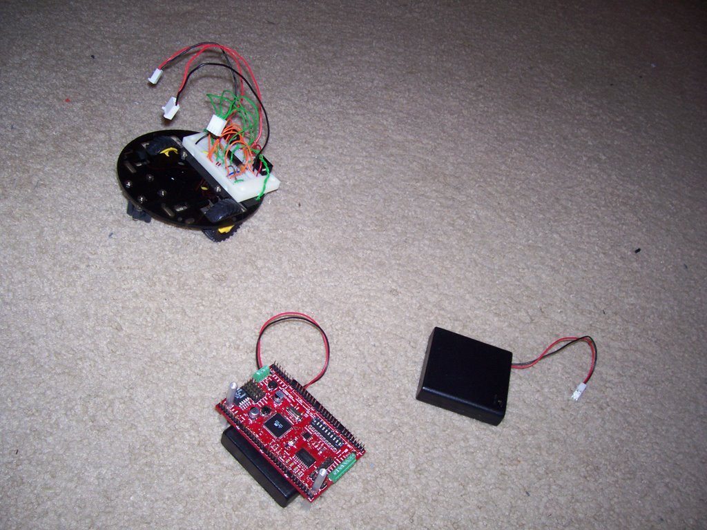
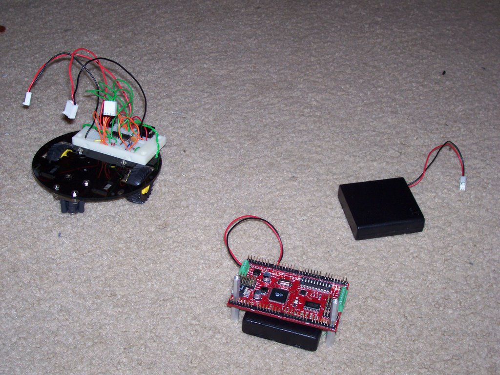
Integrated System
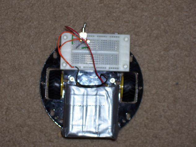
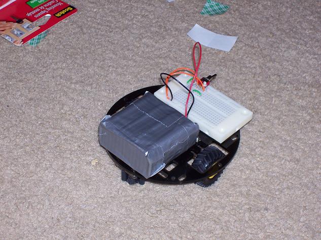
Tracker is equipped with a wide array of sensors, which have been mounted to minimize the sensory dead zones and maximize the accuracy of the measurements within the constraints of Trackers small size.
The two IR sensors are front mounted. They employ a fairly unsophisticated obstacle avoidance technique. If an object is within 16” of the target, the pin goes high and the robot turns away from the object. The actual detection range is based primarily on the lighting conditions and the code loop in which the obstacle avoidance code is located.
The robot will get significantly closer to the target when the check is placed at the end of the while loop, as is the case with the light tracking code. This was very useful in the RF tracking routine where 16” is approximately the effective range of the robots tracking ability. Placing the check for obstacle avoidance appropriately, the robot was able to creep closer to the target (within several inches) without being forced to turn away.
The photovoltaic cells are mounted on the upper-deck of the robot and are attached by solder to two 22 AWG wires. This configuration allows the position of the cells to be easily adjusted which is extremely helpful to prevent the robot from following its own shadow. The coding was heavily simplified by using the analog comparator which conditioned the data to a degree that the coding amounted to a loop in which the robot checks the value on a single pin. If the value is high, then the robot turns left and if the value is low, the robot turns right. This allows the robot to find an arbitrarily located dark area as well as run away from active, moving light sources like flashlights. The code also had “short term memory”. The robot would store the direction it was last heading in so that if an obstacle avoidance situation occurred it would try to avoid contact in that direction. This increased the accuracy of light tracking substantially.
Mobile Platform
The robot was based on Pololu 5” robot chassis. The small size was chosen in order to make the robot as discrete as possible. While this was meant to make it easier to visualize the robot’s role in clandestine operations it really amounted to a significant design challenge.
With only 5” of space to work with (less of one subtracts the space necessary for the wheels and their mounting points) a great deal of effort was used just to get the sensors mounted. Also, the extremely small size of the robot is another reason for systematic inaccuracies in my RF readings. The motors themselves produce RF noise that not only interferes with the analog readings of the receivers but are also completely unpredictable.
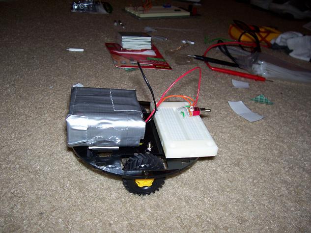
The use of a bypass capacitor (10uF) helped reduce the noise substantially, resulting in fewer microprocessor resets but still producing a large amount of error in the context of a system that requires extreme accuracy of the input values. The small size of the robot also decreased room for modularity. In order to get everything in place, several non-ideal mounts was necessary, including the LCD which was placed in the only available space.
Yet another problem with a small platform is that it reduced the size and quantity of batteries that I was able to use. This leads to quite a few power related issues. When all the systems are running, the robot has a battery life of less than ten minutes. After this point, it is difficult to tell which systems are currently running and which have fallen below the experimental lower limit of operation (approximately 4.65V). Until I began actively monitoring the robot’s power, it made it very difficult to differentiate between problems that were the result of coding and those problems that were the result of system failure due to low power.
Given another opportunity I would highly suggest that a student uses a larger platform, especially if they do not have an exact specification for the amount of space they may need.
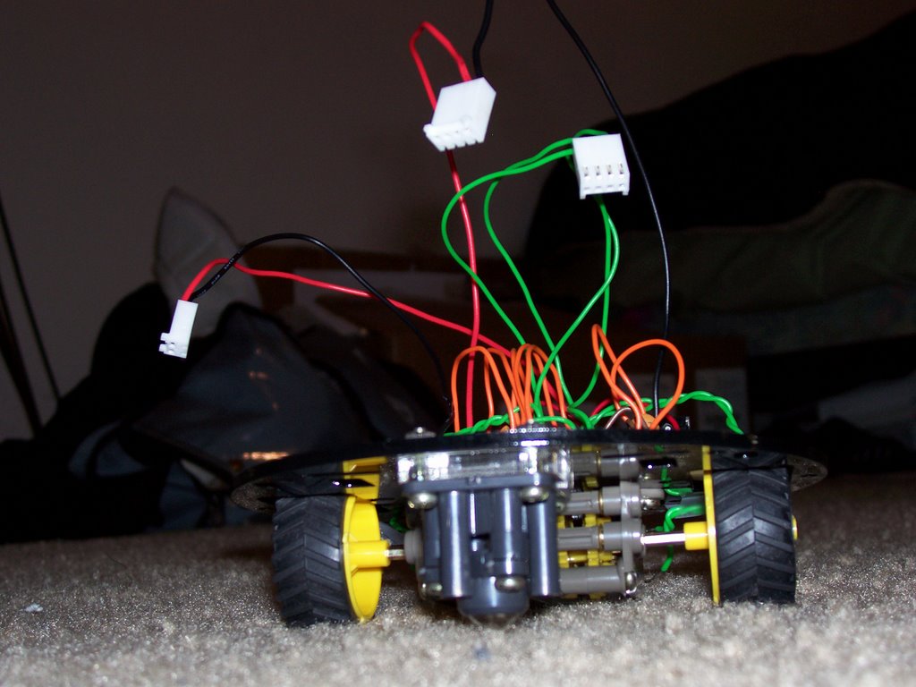
Actuation
A Tamiya twin motor gearbox, ball caster and truck tires were used for locomotion. The motors will be controlled electronically by an SN754410 Quadruple Half H-Driver. This H-Bridge can drive up to 1A of current and has a wide supply voltage rated from between 4.5V and 36V. These drivers were excellent, surviving quite a few crossed-wires and the feedback of a dying motor.
The ball caster allowed the robot to have 360 degrees of rotation, which was another useful feature when it came time to write the tracking code. The robot did not have to be moving in order to spin along its axis, which was helpful in increasing the codes accuracy. The Tamiya gearbox also functioned well, it provided ample power (it had a 58:1 gear ratio) and it held up well to the weight that was applied to it.
The only problem that I had with the gearbox is that because it was mounted so close to the ground it had a tendency to suck in hair and dust particles, which resulted in it becoming completely locked after some of that hair found its way into the motors. When I replaced the gearbox and motors I made certain to close the gears so that the problem would not reoccur.
Sensors
1 - Infrared
Sensor Name: GP2Y0D340K IR Sensor - 16" Trigger
Figure 1.a
Figure 1.b - Wiring Diagram
Vendor
Hobby Engineering
180 El Camino Real
Millbrae, CA 94030
1-866-ROBOT-50 (toll-free 866-762-6850)
Objective(s)
Two IR sensors were purchased to serve as Tracker's 'eyes'. Functionally, they ensure that Tracker stays at least 16" away from any of the objects that they detect.
Theory
These IR sensors are used in the typical fashion. When the robot gets within 16" of a target the output line goes high. The robot uses this information to send a signal to the motor that then turns in order to avoid collision with the object.
Scope
Two IR triggers are mounted on either side of the robot for collision detection.
2 - Radio Frequency Transmitter/Reciever (Special Sensor 1)
Sensor Name: RF-KLPA 4800bps
Figure 2.a Transmitter Figure 2.b Receiver
Figure 2.c - Wiring Diagram
Vendor
1-303-284-0979
Spark Fun Electronics
2500 Central Ave.
Suite Q
Boulder, CO 80301
Objective(s)
The main 'special' sensor on Tracker. The transmitter will be deployed on an external 'beacon' unit. It will transmit a signal to the two receiver units mounted on Tracker. Tracker will use this information to determine the location of the external beacon.
Theory
In theory, the two receiver units, located on either side of tracker should receive slightly different amounts of power since they are not directly facing the signal source. As of the writing of this report, I plan to exploit this presumably small difference in power by 'tapping' the antennae line (pin 8 on the receiver diagram) and running the resulting voltage through an LM339N comparator. This device (described in the section on photovoltaic cells), has already proven capable of resolving voltage differences as low as a hundredth of a volt. It seems likely that as long as the antenna receives an analog voltage that is linearly related to the distance from the source that this technique can be used to find the direction (left or right) between the transmitter and receiver pairs. Further testing has proved that there are a great deal of external variables that makes this simple resolution of voltages nearly impossible to apply in practice.
Scope
Two receivers and a single transmitter will be used. The receivers should be capable of resolving whether the robot should move either left or right.
3 - Photovoltaic Cells (Special Sensor 2)
Sensor Name: BPW-34 clear-epoxy solar cells
Figure 2.a
Figure 2.b - Block Diagram LM339N
Figure 2.c - Circuit Diagram LM339N
Dimensions: 1/8"
Vendor
1-866-ROBOT-50 (toll-free 866-762-6850)
Hobby Engineering
180 El Camino Real
Millbrae, CA 94030
Objective(s)
These photovoltaic cells (2) small (1/8") solar cells. They produce a voltage that has been measured between .25 and .38V (theoretically, in direct sunlight, they should be capable of producing up to .77V). They are being used as an optical switch.
Theory
In their normal state, the solar cells are only capable of producing a voltage. However, using an LM339N Comparator, running the positive terminals of each solar cell to the V+ and V- inputs and using an external pull-up resistor they are
capable of producing logic high or low depending on which cell is receiving the most light. Another advantage of this circuit is that since the cells produce power on their own, they do not draw on any external power source. While this is a small difference, in the scope of things, it is a positive side-effect.
I also theorize that the photovoltaic cells have a faster 'reaction' time compared to the historically 'slow' CDS cells, making them a handy replacement for the usual work-horse of light tracking.
Scope
Two photovoltaic cells are being used to resolve the directions left and right.
Data
Experimental Voltages:
.01V with no significant ambient light
.25V with moderate light (well lit room)
.40V direct exposure to a flashlight
.77V theoretical maximum voltage when exposed to direct sunlight.
Under normal experimental conditions these solar cells operated between .25V and .30V.
Experimental Current
Using a 1000Ohm DIP package resistor
Negligible (outside of the voltmeter’s resolution) drive current for the solar cells.
As a note to those who may want to use photovoltaic cells like these for powering circuitry or significant light tracking on solar power alone. In order to use these successfully in those applications one must use several (theoretically six, but very likely many more than that) in series. These will only produce at maximum of .77 volts and a very low current. Also, one would do well to use a voltage trigger like the 1381E (rated for 2.2V) and a Miller Engine in order to store power. That way your circuitry can remain idle until enough power is collected through the Miller Engine and then your robot will turn on in “bursts”. Selecting the appropriate trigger voltages and using a significant amount of solar cells will reduce the idle time between these bursts.
Behaviors
The robot will have four main behaviors.
Target acquisition: The robot will determine the location of a beacon and rotate in the direction of the target.
Tracking: Once acquired, the robot will try to keep a safe distance from the target and will adjust its speed in order to maintain proximity.
Obstacle Avoidance: Basic obstacle avoidance behaviors will be available.
Hiding: If the robot is within a dangerous proximity of the target, it will search for a corner of the room with the smallest amount of light this will provide an end of program loop in which the robot continues to search for the darkest area available to it at any give moment.
Experimental Layout and Results
Two experiments were conducted for this robot. The first was testing the effective voltage and current of the photovoltaic cells. The experiment was conducted in three different lighting conditions: low light (darkened room with limited to no ambient light source), normal light (a well light room with two 40 Watt bulbs), and high light (direct exposure to a flashlight.
(1) Photovoltaic Cells
The photovoltaic cells were surprisingly consistent; the full results of the experiments are presented below.
Experimental Voltages:
.01V with no significant ambient light
.25V with moderate light (well lit room)
.40V direct exposure to a flashlight
.77V theoretical maximum voltage when exposed to direct sunlight.
Under normal experimental conditions these solar cells operated between .25V and .30V.
Experimental Current
Using a 1000Ohm DIP package resistor
Negligible (outside of the voltmeter’s resolution) drive current for the solar cells.
(2) Radio Frequency
The second experiment involved testing the analog values received at the two receivers at various ranges after these values were recorded for one minute with direct line of sight between the receiver and the transmitter. The results of which are presented below (measured in Volts).
Directly In Front (Right) Directly In Front (Left) Side (Right) Side (Left)
1” .93 – 1.31 1.17 – 1.21 1.75 – 2.04 1.19 – 1.31
5” 1.19 – 1.39 1.18 – 1.19 1.19 – 1.46 1.43 – 1.47
12” 1.17 – 1.32 1.17 – 1.19 1.12 – 1.19 1.34 – 1.38
24” 1.23 – 1.30 1.08 – 1.09 1.09 – 1.26 1.19 – 1.20
The upshot of these results is that under no conditions were the two receivers consistent even in terms of themselves. At any given point (except during the extreme case of 1” which coincidentally is where the tracking code works the best) the ranges of these values will overlap in unpredictable manners.
Also, it should be noted that on average, the left receiver was both more consistent and received much less of the analog signal than the right receiver. It is results such as these that are the reasons that the system fails to function in quite a few cases.
Conclusion
At the conclusion of this experiment I believe that I was able to accomplish a great deal of work on explaining why triangulation may be the only accurate method of using Radio Frequency waves as a mode of tracking. My work managed to accentuate all the problems associated with monopole tracking of an object via RF.
The nature of radio frequency itself seem to preclude using one data point in order to track an object. Since Radio Frequency is a wave it behaves as such with unpredictable reflections. The relatively high strength of the transmitter and the low effective range of accurate analog measurements provide a difficult to surmount contradiction. In order to get accurate analog measurements one has to be close (at an absolute maximum of two feet), but the closer one gets the more likely the analog measurements are to be experimentally identical (making the comparator useless). For this reason, the robot tended to do well until making its final approach to the target; at that point it would veer off at some angle and move directly away. More data points are absolutely crucial to getting viable data from these sensors.
What I am very proud of is my work with light tracking. The relatively simple light tracking circuit has a switching time on the order of microseconds as opposed to CDS cells which switch at closer to a millisecond. Photovoltaic cells could easily be expanded to be used as a replacement for CDS in line tracking robots. They have a longer range (they were highly sensitive up to a yard in normal light) and seem to behave much more accurately than CDS cells. Also, combined with a Miller Engine, this configuration could be used to create a light-tracking, solar powered robot. The applications for this new mode of light detection are substantial.
If someone were to try to design an RF tracking robot in the future I would most certainly attempt to use some form of triangulation. Without several data points to check against there is no way to guarantee or even to expect an acceptable level of accuracy.
If, however, one were to try a similar method as my own I would highly suggest using a larger platform and shielded wiring. Every bit of noise around the receivers must be cancelled out if any chance of receiving accurate values is possible. Also a significantly larger platform would allow you to baffle the receivers such that the angle at which they could receiver is reduced to a point. Any greater angle of reception would almost certainly lead to experimentally identical values for the receiver pair, making the use of a comparator impossible.
The most glaring technical limitation of my work was financial. Upon further reflection it seems that the use of a larger number of sensors in conjunction with RF may have increased the odds of detection. Specifically, a compass would have allowed the robot to know it was heading in the last known “good” direction as opposed to veering off along another signal strength line. Also a greater number of beacons and some type of sonar would have been an ideal sensor suite to guarantee proper localization. The time between sonar pings could be used with the result of RF pings to determine location and distance from a target relative to other beacons. This configuration is used widely in swarm robots and it would have been an excellent addition to this platform.
Documentation
D. Cook, "XS Boost, A Chef’s Salad Solar Robot," [Online document], Date not provided, [cited 2006 Aug 1], Available HTTP: http://www.robotroom.com/XSBoost.html
Spark Fun Electronics, "My First Robot,” [Online document], No Date Provided [cited 2006 Aug 1], Available HTTP: http://www.sparkfun.com/commerce/present.php?p=Robot%20Building%20Page1
Arduino Development Team, "Arduino – Howto, ”[Online document], No Date Provided, [cited 2006 Aug 1], Available HTTP: http://www.arduino.cc/en/Main/Howto
MIT, "The Cricket Indoor Location System,” [Online document], 2004 July, [cited 2006 Aug 1], Available HTTP: http://cricket.csail.mit.edu/
J. McLurkin, "Retired Robots – The Ants,” [Online document], No Date Provided, [cited 2006 Aug 1], Available HTTP: http://www.ai.mit.edu/projects/ants/index.html
Appendices
Motor Test Code
#include
#include
#include
#include
#include
#include
//#include
#include
#include
#include
#include
#include
volatile uint16_t ms_count;
unsigned int duration = 0;
/*
* millisecond counter interrupt vector
*/
SIGNAL(SIG_OUTPUT_COMPARE0)
{
ms_count++;
}
SIGNAL(SIG_OUTPUT_COMPARE2)
{
duration++;
}
void ms_sleep(uint16_t ms);
void set_duration(uint16_t match);
void init_timer(void);
void init_timer_two(void);
unsigned int motor_control(unsigned int speed, unsigned int direction);
void turn_left();
void turn_right();
void motor_brake();
const unsigned int reverse = 1;
const unsigned int forward = 2;
const unsigned int left = 3;
const unsigned int right = 4;
const unsigned int brake = 5;
const unsigned int stop = 100;
unsigned int speed = 0;
unsigned int direction = 2;
unsigned int change = 0; //speed change
int main(void)
{
init_timer();
init_timer_two();
//USART_Init();
//delay_ms(500);
sei();
ms_sleep(712);
DDRB = 0x01; /* enable PORTB 1 as an output */
DDRD = 0xFF;
PORTB = 0x01;
//unsigned int data = 0;
int test1 = 0;
int test2 = 0;
int test3 = 0;
int test4 = 0;
//unsigned int current_state = 0;
for (;;)
{
TCNT2 = 0;
duration = 0;
if (test1 == 0)
{
while (duration < 1166)
{
motor_control(speed, forward);
//current_state = forward;
if (duration > 800)
motor_brake();
//ms_sleep(speed);
}
test1 = 1;
}
TCNT2 = 0;
duration = 0;
while (duration < 1000)
{
motor_control(speed,reverse);
if (duration > 800)
motor_brake();
//ms_sleep(speed);
}
turn_left();
turn_left();
motor_brake();
turn_right();
turn_right();
change = stop;
motor_brake();
break;
}
for (;;)
ms_sleep(200);
}
/*
* ms_sleep() - delay for specified number of milliseconds
*/
void ms_sleep(uint16_t ms)
{
TCNT0 = 0;
ms_count = 0;
//duration++;
while (ms_count != ms)
;
}
void set_duration(uint16_t match)
{
TCNT2 = 0;
duration = 0;
//duration++;
while (duration != match)
;
}
void turn_left()
{
duration = 0;
TCNT2 = 0;
while (duration < 200)
{
PORTD = _BV(PIND0) | _BV(PIND3);
}
}
void turn_right()
{
duration = 0;
TCNT2 = 0;
while (duration < 200)
{
PORTD = _BV(PIND1) | _BV(PIND2);
}
}
void motor_brake()
{
PORTD = 0x00;
// if (change => 100)
// {
// PORTD = 0x00;
// }
change = change + 100;
speed = change;
ms_sleep(speed);
}
unsigned int motor_control(unsigned int speed, unsigned int direction)
{
if (direction == reverse)
PORTD = _BV(PIND0) | _BV(PIND2);
if (direction == forward)
PORTD = _BV(PIND1) | _BV(PIND3);
if (direction == right)
turn_right();
if (direction == left)
turn_left();
return 0;
}
/*
* initialize timer 0 to generate an interrupt every millisecond.
*/
void init_timer(void)
{
/*
* Initialize timer0 to generate an output compare interrupt, and
* set the output compare register so that we get that interrupt
* every millisecond.
*/
TIFR |= _BV(OCIE0);
TCCR0 = _BV(WGM01)|_BV(CS02)|_BV(CS00); /* CTC, prescale = 128 */
TCNT0 = 0;
TIMSK |= _BV(OCIE0); /* enable output compare interrupt */
OCR0 = 125; /* match in 1 ms */
}
/*
* initialize timer 0 to generate an interrupt every millisecond.
*/
void init_timer_two(void)
{
/*
* Initialize timer0 to generate an output compare interrupt, and
* set the output compare register so that we get that interrupt
* every millisecond.
*/
TIFR = _BV(OCIE0) | _BV(OCIE2);
TCCR2 = _BV(WGM21)|_BV(CS22)|_BV(CS20); /* CTC, prescale = 128 */
TCNT2 = 0;
TIMSK = _BV(OCIE0) | _BV(OCIE2); /* enable output compare interrupt */
OCR2 = 125; /* match in 1/100 second */
}
Obstacle Avoidance Functions
int main(void)
{
init_timer();
init_timer_two();
//USART_Init();
//delay_ms(500);
sei();
ms_sleep(712);
DDRB = 0x01; /* enable PORTB 1 as an output */
DDRD = 0xFF; //Enable PORTD as an output port (MotorControl)
DDRC = 0xFC; //Enable PORTC 0 and PORTC 1 as input (Sensors)
//DDRA = 0xFE; //Enable PORTA 0 as input (Light Follow)
PORTB = 0x01;
//unsigned int data = 0;
int test1 = 0;
while (test1 == 0)
{
if (PINC == 0x03)
{
ms_sleep(200);
if (PINC == 0x03)
test1 = 1;
}
}
//unsigned int current_state = 0;
for (;;)
{
TCNT2 = 0;
duration = 0;
while (obstacle == 0)
{
motor_control(speed, forward);
obstacle = avoid();
}
avoid();
}
for (;;)
ms_sleep(200);
}
int avoid()
{
duration = 0;
TCNT2 = 0;
if (PINC == 0x03)
{
obstacle = 0;
return 0;
}
if (PINC == 0x01)
{
while (duration < 200)
motor_brake();
motor_control(speed, left);
}
if (PINC == 0x02)
{
while (duration < 200)
motor_brake();
motor_control(speed, right);
}
if (PINC == 0x00)
{
while (duration < 200)
motor_brake();
turn_left();
turn_left();
}
return 0;
}
Final Revision (Light Tracking Code)
int light_follow()
{
if (light_token == 0)
{
print_message("Light Tracking -- Active", 24);
light_token = 1;
}
duration = 0;
TCNT2 = 0;
int hospital = 0; //obstacle
if (PINA == 0x00)
{
light_left++;
if (light_left == 10)
{
light_left = 0;
light_right = 0;
last_direction = 0; //Stores where the robot was heading
quick_left();
hospital = avoid_test();
if (hospital == 0)
{
TCNT2 = 0;
duration = 0;
while (duration < go_time && obstacle == 0)
{
motor_control(speed, forward);
obstacle = avoid_test();
// if (duration > (go_time/2) )
// hospital = avoid_test();
}
}
}
}
if (PINA == 0x01)
{
light_right++;
if (light_right == 10)
{
light_left = 0;
light_right = 0;
last_direction = 1; //Stores where the robot was heading
quick_right();
hospital = avoid_test();
if (hospital == 0)
{
TCNT2 = 0;
duration = 0;
while (duration < go_time && obstacle == 0)
{
motor_control(speed, forward);
obstacle = avoid_test();
if (duration > (go_time/2) )
hospital = avoid_test();
}
}
obstacle = hospital;
}
}
return 0;
}
posted by Steve Spalding at 5:51 PM
|
0 comments
![]()